F200 Wiring Harness Connection Guide
F200 Wiring Harness Connection Guide
This document will continuously update the hardware connections of Sveaverken F200 Auto Steer System.
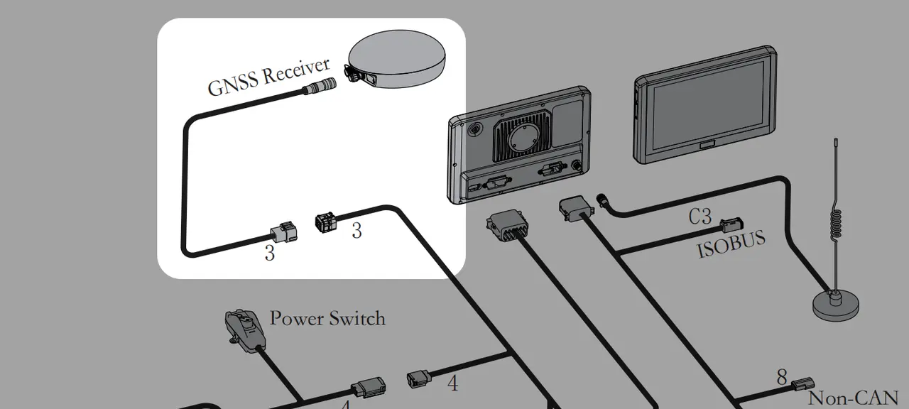
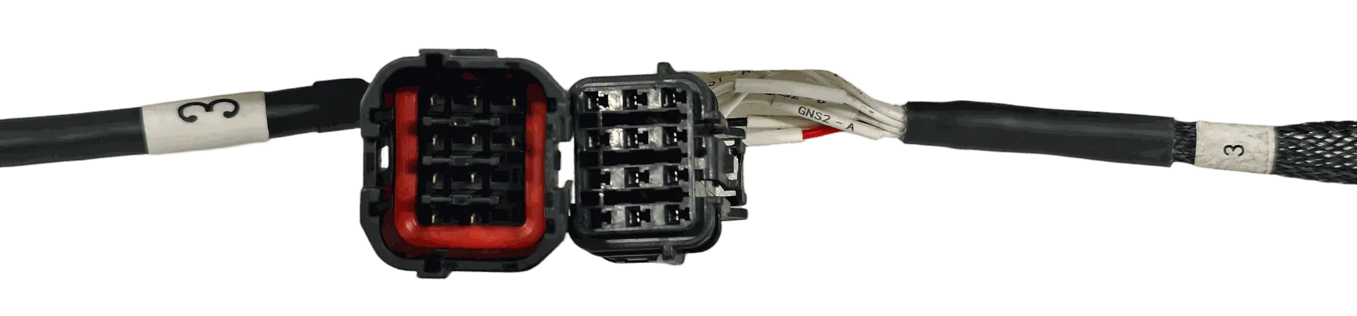
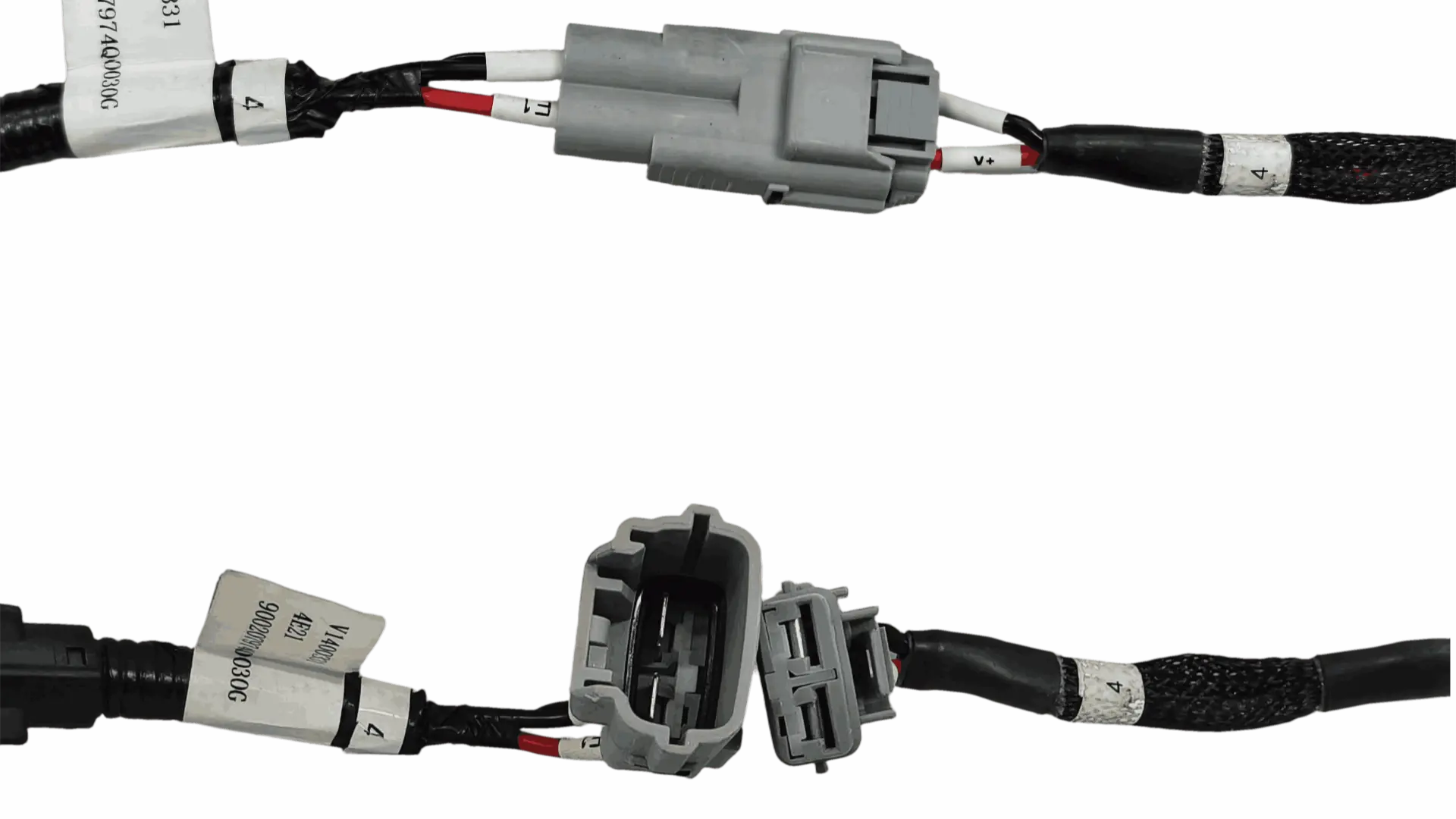
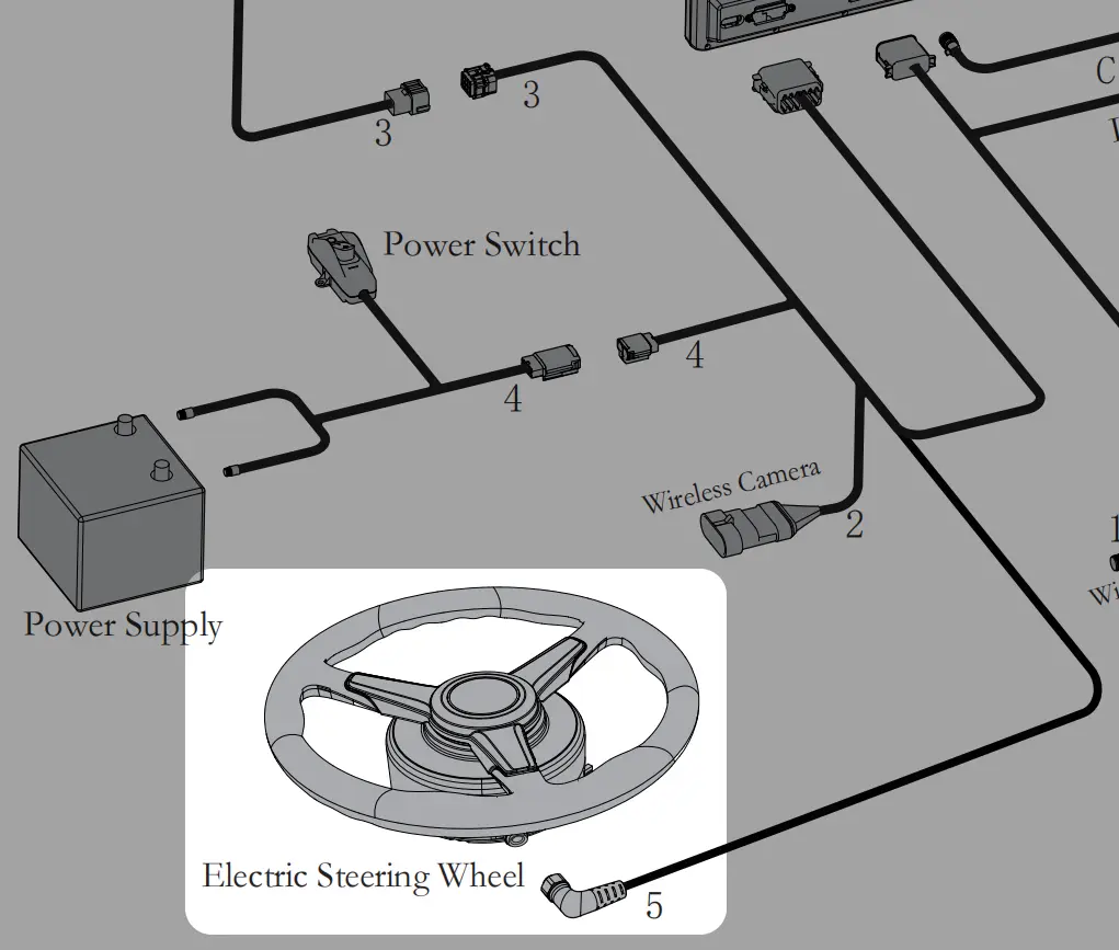
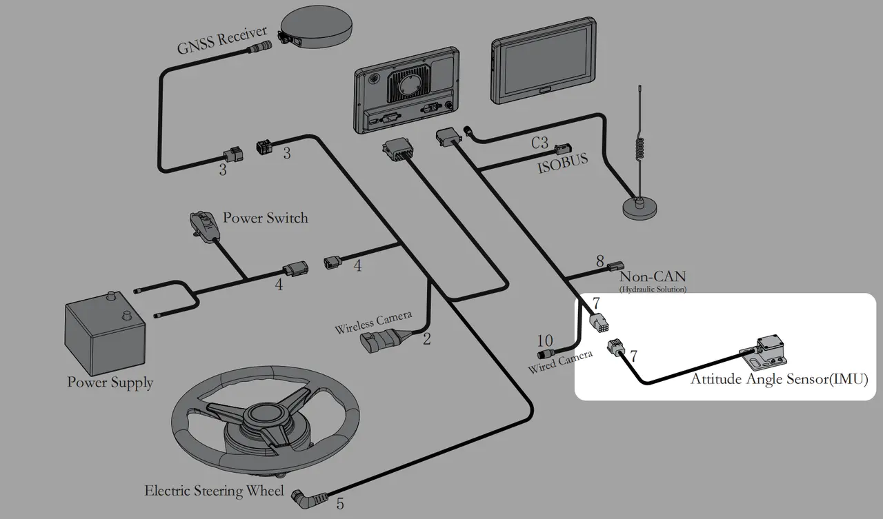
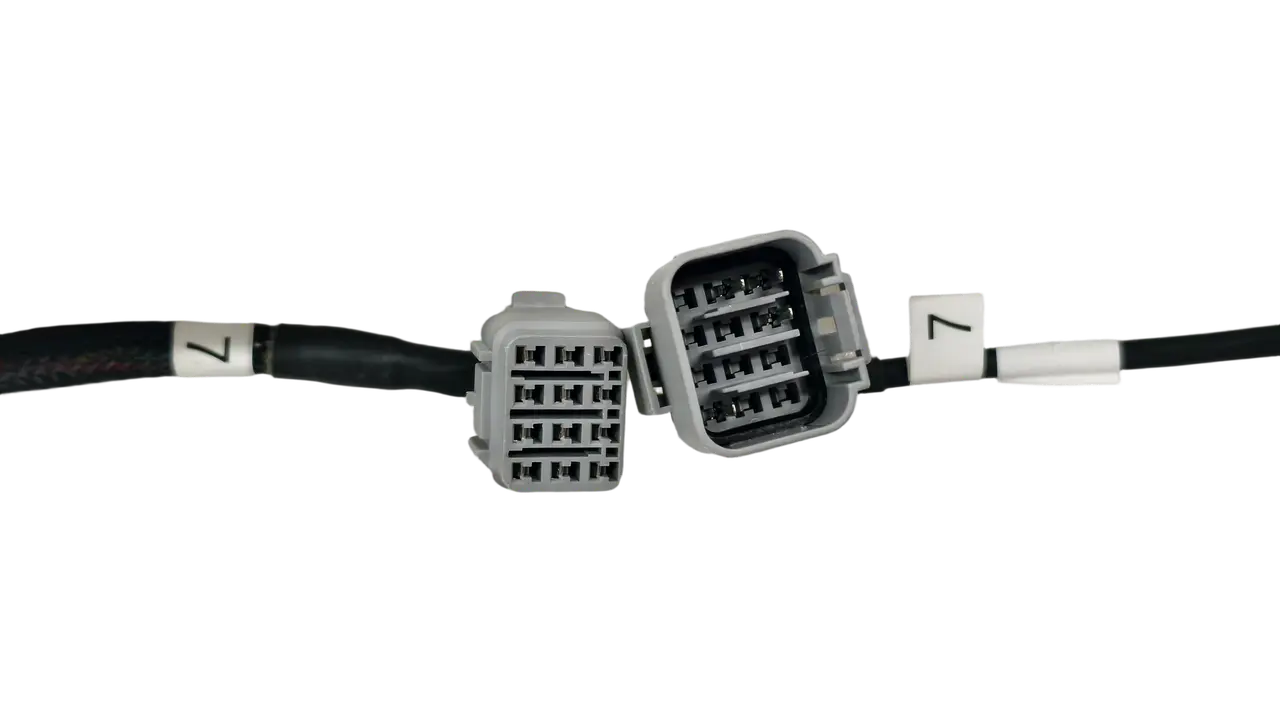
Refer to the instructions below. The core rule for wiring connections is to mate interfaces with the same number.
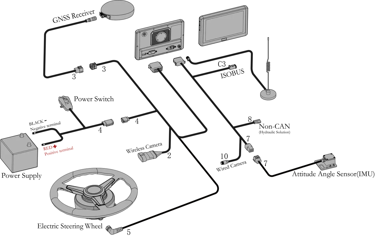
Here are some physical diagrams to help you install the corresponding physical items.
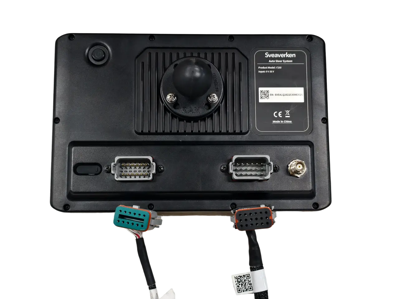
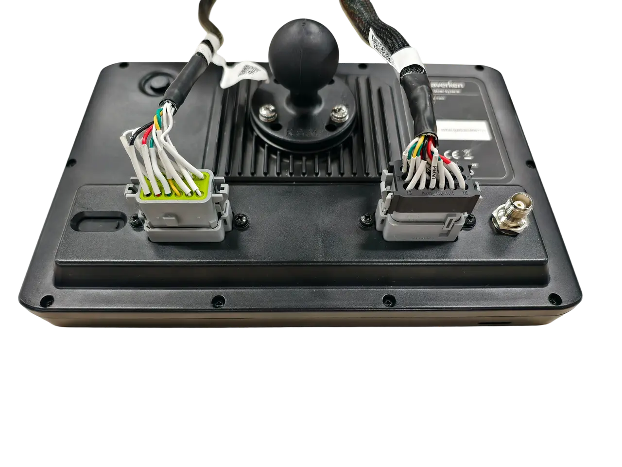
Display Terminal
Port 3: GNSS Receiver

Port 4: Power Supply Interface

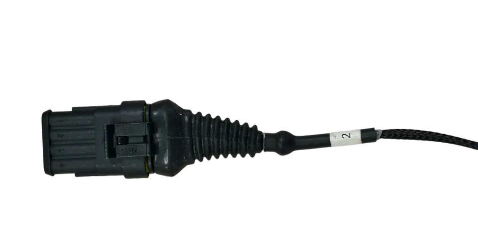
Port 2: Power supply port for wireless camera
Not included as standard equipment; please ignore if not present on the actual device

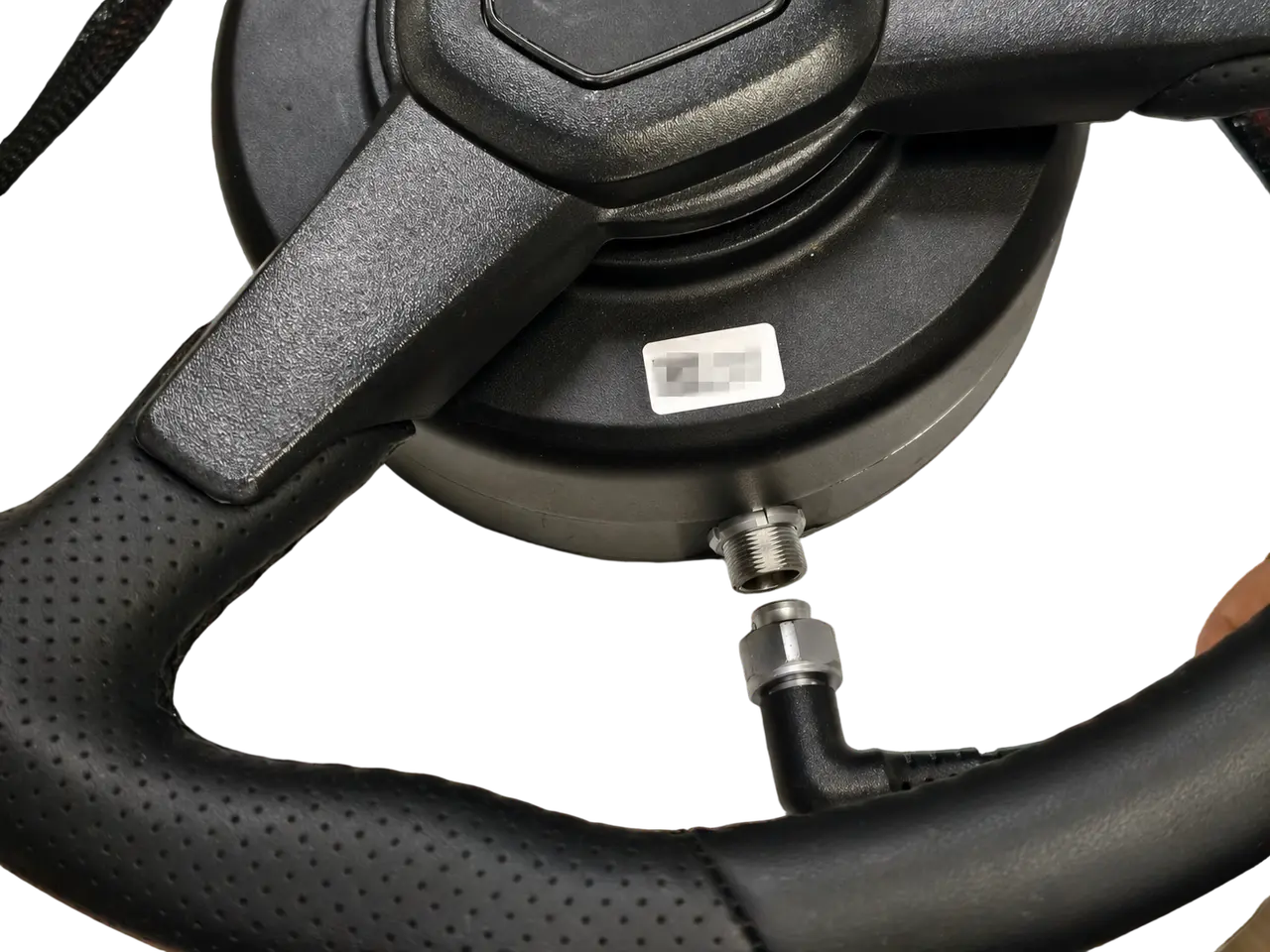
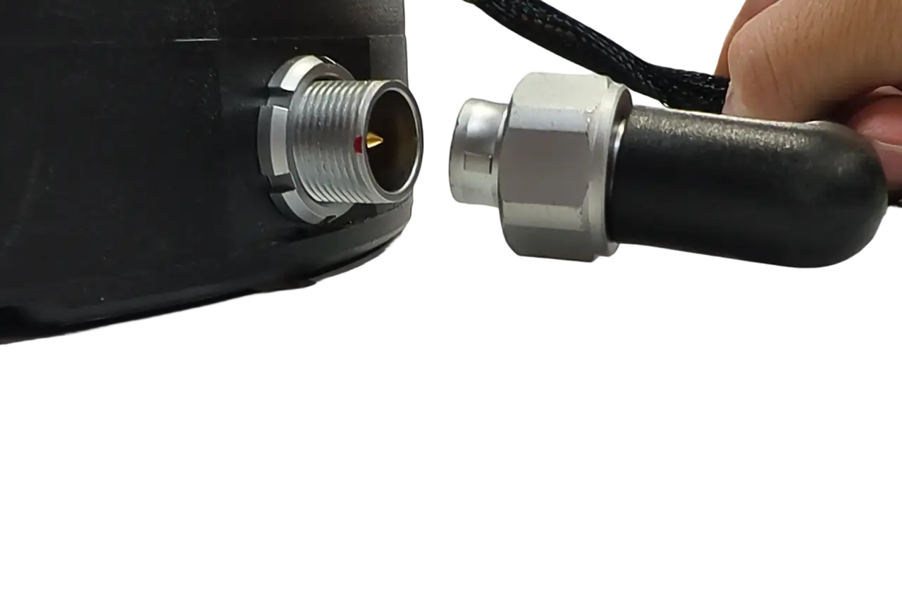
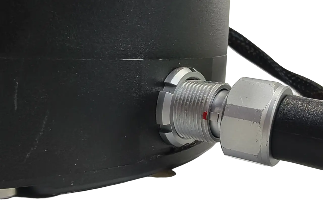
Port 5:Electric Steering Wheel Motor
Align with the red dot, insert into the motor interface, and tighten the fixing screw clockwise.
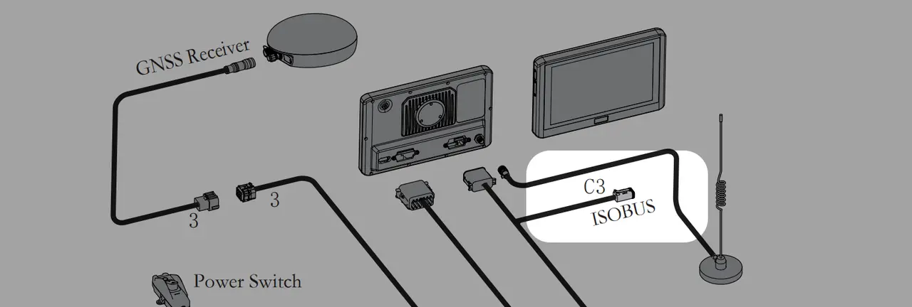
Port C3: Connect ISOBUS-related devices

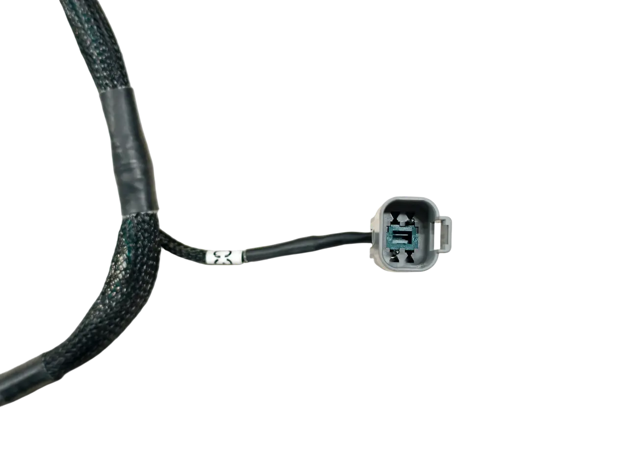
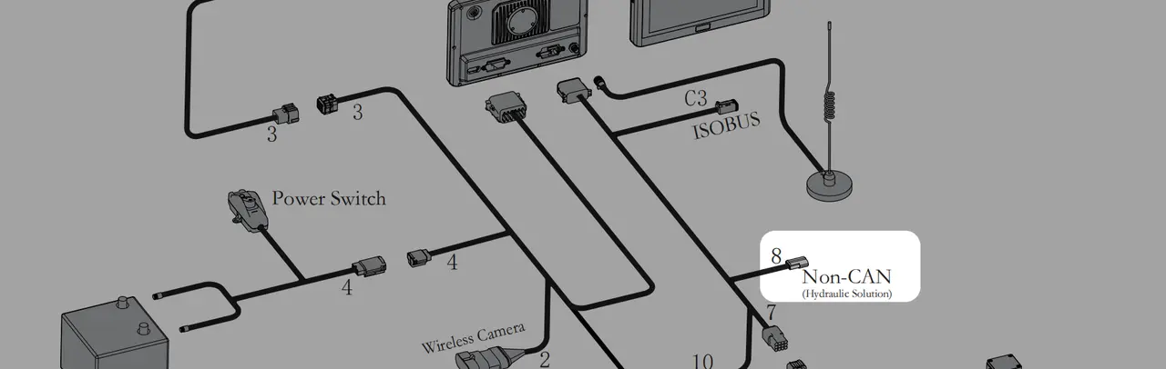
Port 8: Non-CAN Hydraulic Solution
Data interface for hydraulic steering solution, non-standard configuration. Please ignore it if it is not equipped on the actual device.
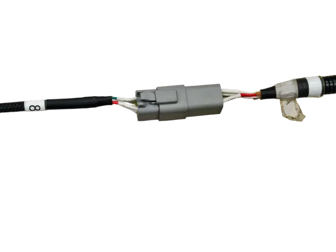
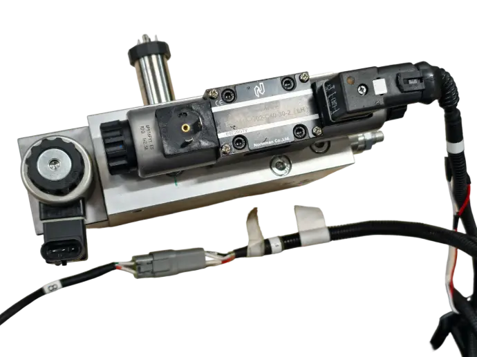
SVEA hydraulic valve, for illustration only, subject to the actual product
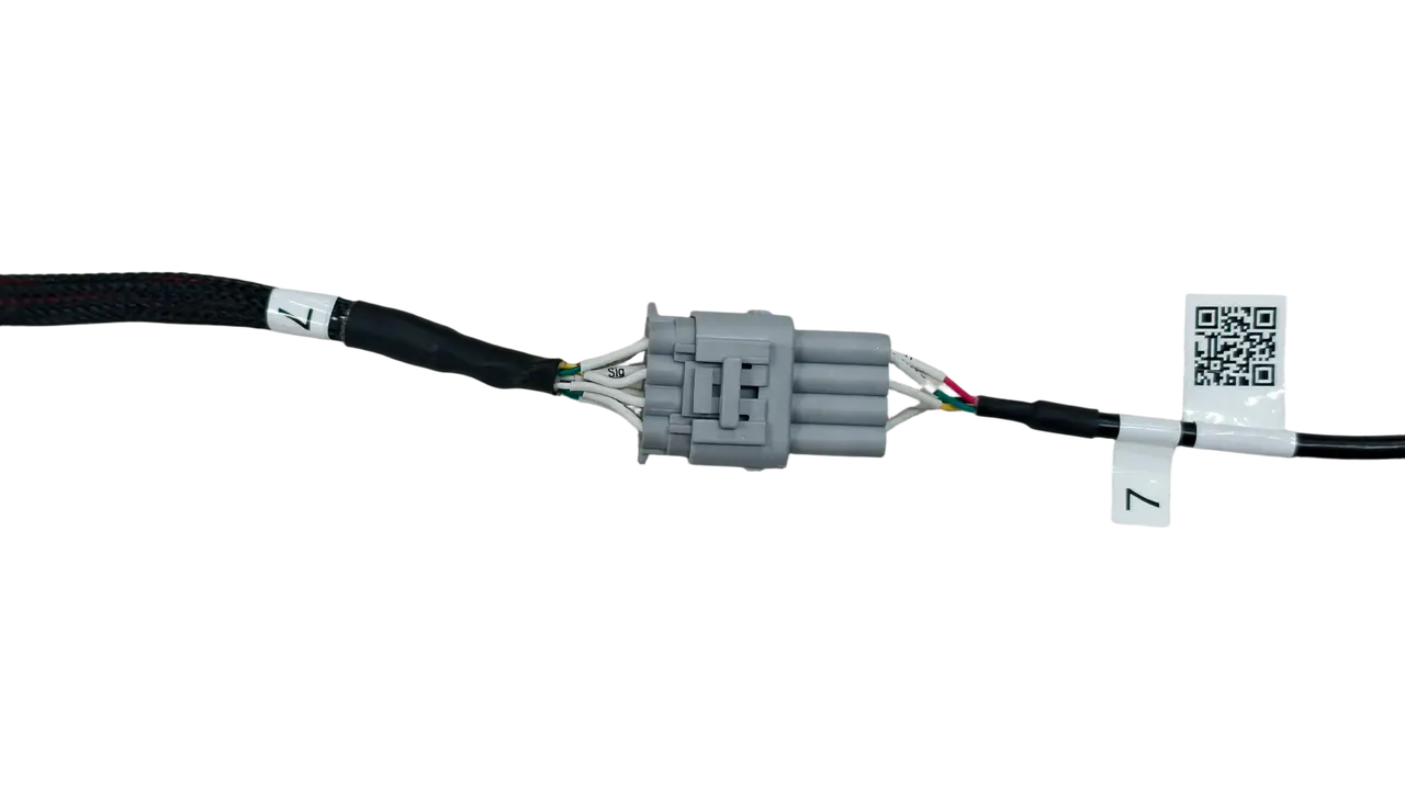
Port 7: Attitude Angle Sensor (IMU)
Used to connect angle sensors, implement GNSS sensors, and other devices.
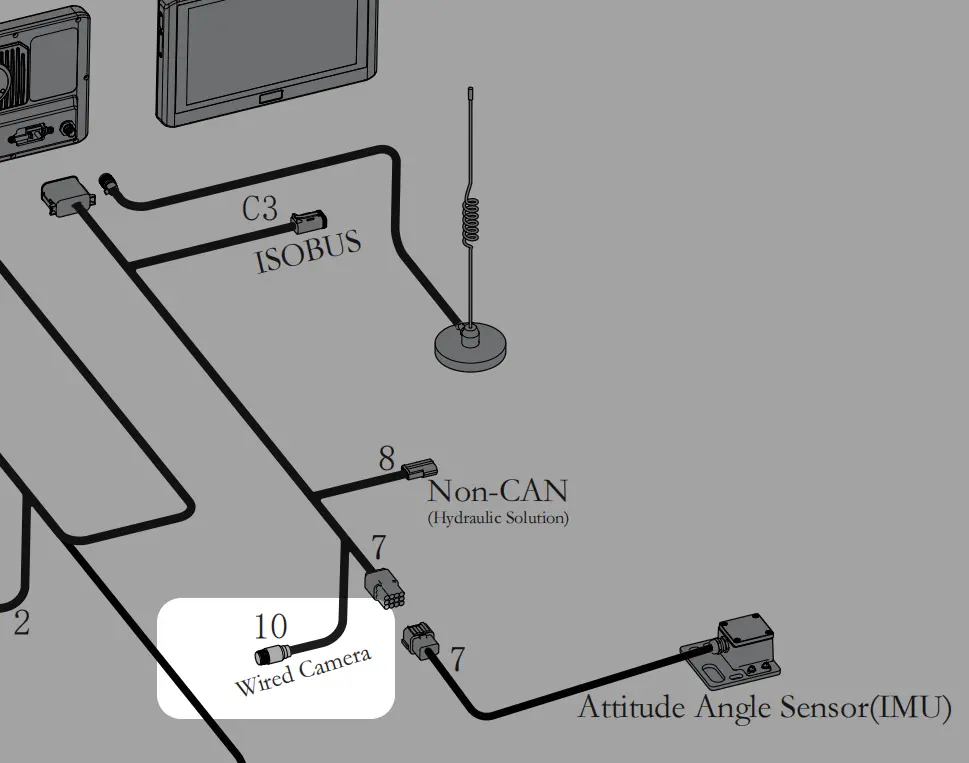
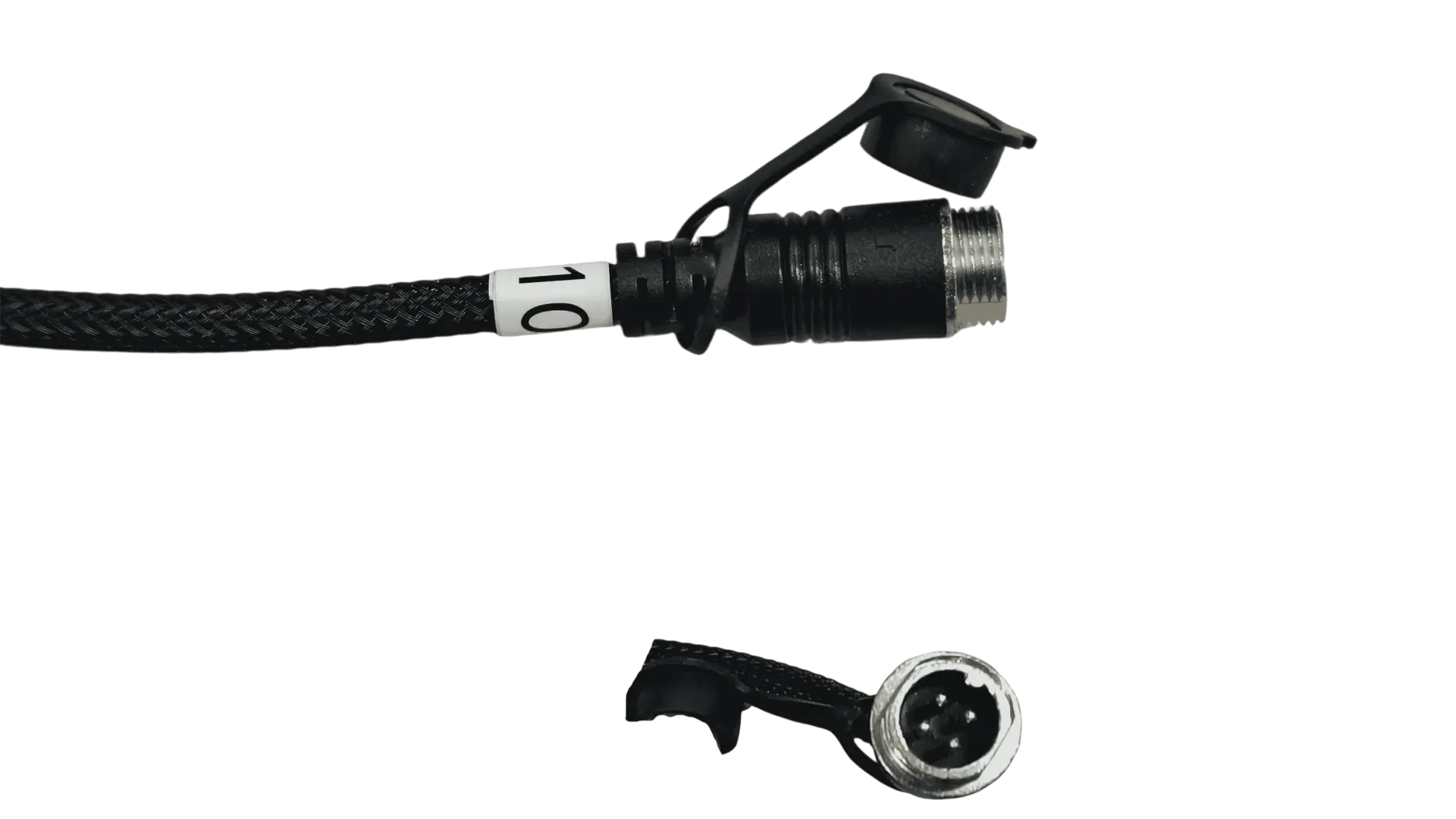
Port No.10: Wired Camera
An interface for connecting wired cameras, responsible for camera power supply and data transmission, 4PIN design.